This is long, but it’s important to understand. Take for example a Form Fill and Seal packaging lines operate at temperatures below 650°F. A traditional cartridge heater for this application would use a stainless-steel case material, rated to 1,472°F.
Stainless steel is excellent at corrosion and oxidation protection because it uses Chromium which forms a Chromium Oxide layer on the surface and protects the metal. However as a heat transfer medium Chromium sucks, with a typical thermal conductivity of 16.1W/m.K @ 100C – much lower than many of the alloys. Even the 4140 alloy which is used in many tools is measured at 42.6W/m.K.
Why does that matter you ask? Well to answer this we must think of the heater as part of the system – where the tool is absorbing the heat energy, the sensor is measuring the temperature and the tool is dissipating heat into an end process as a load.
- The heater internally converts the current flow to heat energy, which transfers the heat to the sheath of the heater via conduction through the insulation material
- Since the heater is inserted into a tool (normally as a slip fit) the heat transfers from the sheath of the heater to the inside of the tool bore at point of contact via conduction, and across the air gap via convection.
- The heat is absorbed by the tool and dissipates within the mass via conduction to the sensor as well as the point of heat loss (load).
Each of these stages takes time for the heat to move through. Conduction is by far the fastest transfer method, convection and radiation are slower. And since the system is under closed loop control by the temperature controller, the sensor needs to report back quickly to manage the power signal being sent to the heater to maintain the best balance of heat input vs loss.
So back to the thermal conductivity. The part with the lowest thermal conductivity in the above system is the heater sheath. This means that this acts as a damper to the rate of heat energy transfer from the core of the heater to the tool itself. And in a process control system that is PID based this is inefficiency.
A closed loop PID temperature controller works by turning on and off the power to the heater at a rate to manage to a set value. Electricity is measured by the wattage consumed over time by the system to maintain that set value. When the controller is not calling for heat, there is no electricity flow, and no watts are being consumed. A data logger would record a graph like this (converting Volts and Amps to Watts).
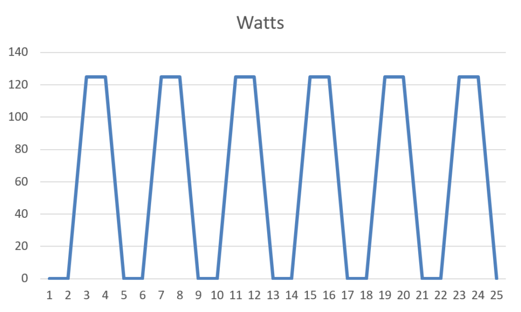
Heaters are designed to produce a specific maximum wattage (i.e. 500W) at a constant power input. In use however the amount of power consumed in the application will be lower depending on the amount of time the power is on – or for those that had the misfortune of experiencing Integral calculus it is referred to the “area under the curve”. That is the electricity you really pay for.
Speeding up the rate of thermal transfer in the system will reduce the time that it takes for heat energy to be reacted to, thus reducing the amount of time the power is being consumed. The below graph shows two systems as a comparison.
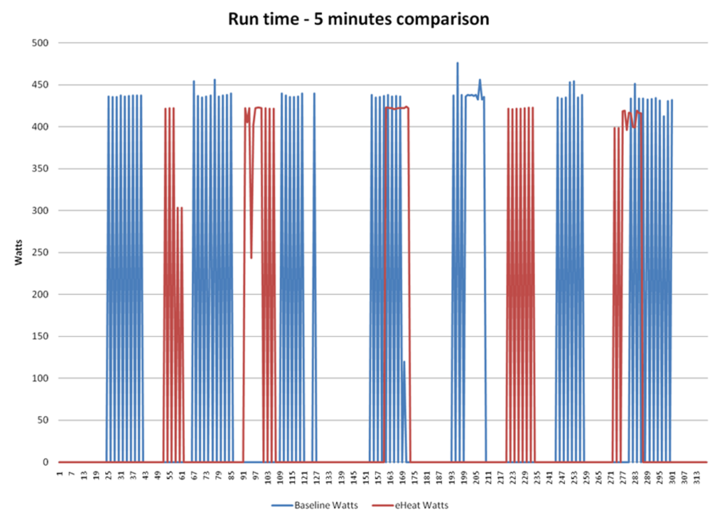
This is actual data from a Form Fill and Seal packaging system comparing two cartridge heaters.
- The blue represents the standard heater construction
- The red represents the unique eHeat design
As you can see the number of pulses of power needed to maintain set point is higher in the blue system than the red system, as well as the actual consumption of power (represented by the area under the line) is higher than the red.
By the numbers:
- Blue power measured at 7.91Wh, with a peak Wattage recorded of 475.9W
- Red power measured at 5.91Wh, with a peak Wattage recorded of 420W
This represents a 25% energy reduction during system operation as well as a lower peak wattage needed to maintain set value.
As they say – the proof is in the pudding. So, we built a test system with two identical packaging jaws, with identical wattage heaters being monitored by power meters and controlled to a set temperature. The following picture shows the set up:
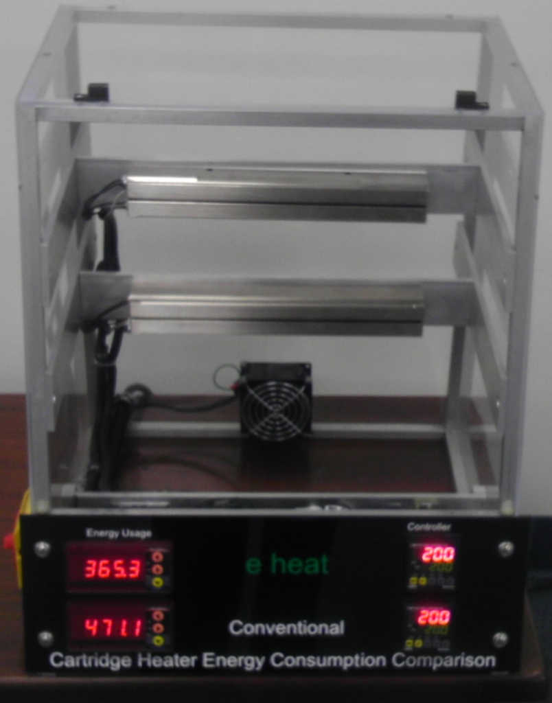
The top heater is the eHeat construction, the bottom is the conventional heater. Each jaw is offset from each other, and the fan draws heat out so it’s not being influenced from the other jaw. Energy usage is shown on the left, set temperature is on the right. In the time this display was running, it recorded a 23% lower energy use in the eHeat construction. This display is set up to run at any of our trade shows, stop by to see it and ask questions.