Trusted Smart Heat Management® for Demanding Industrial Applications. Engineered with passion. Delivered with decades of experience.
Every electric heater used in a complete thermal system requires some means to sense and control the temperature accurately and efficiently. Temperature sensors are an essential component in the thermal management process of any process heating application. Without an accurately placed, properly specified sensor feeding the control loop, even the best heater produces inconsistent temperatures, excessive energy consumption, accelerated wear, and unpredictable process outcomes.
Nexthermal designs and manufactures build-to-order, as well as off-the-shelf temperature sensors — thermocouples (TC), resistance temperature detectors (RTDs), and thermistors — specifically matched to the thermal systems and applications we serve. Because we manufacture both the heater and the sensor, we understand how these two components interact at the system level. We specify sensors for placement, probe geometry, sheath material, junction type, and cable construction that are optimized for your exact operating conditions.
These are not catalog sensors retrofitted to a heater specification. They are purpose-engineered sensing solutions designed to deliver the accuracy, response time, and service life your application demands.
Connect with an Application Engineer to specify a sensor matched to your thermal system.
Selecting the correct sensor technology is an important engineering decision in any thermal system design. Each type has distinct operating characteristics that determine its suitability for a given application.
Thermocouple Temperature Sensors – Type J & Type K
A thermocouple temperature sensor is the most widely used temperature sensing technology in industrial heating applications. Thermocouples generate a small electrical voltage (EMF) that is proportional to the temperature difference between the sensing junction (hot junction) and the reference junction (cold junction). This signal is measured by a temperature controller, PLC, or process instrument to provide accurate and reliable temperature monitoring.
Because of their wide temperature range, fast response time, durability, and cost-effectiveness, thermocouple sensors are commonly used in plastics processing equipment, packaging machinery, hot runner systems, industrial ovens, food processing equipment, and other OEM heating applications.
Nexthermal manufactures custom Type J and Type K thermocouple sensors in a wide variety of sheath materials, mounting configurations, lead wire options, and termination styles to meet demanding industrial environments.
Type J Thermocouple (Iron / Constantan)
Temperature Range: -40°F to 1,382°F (-40°C to 750°C)
Type J thermocouples are a proven solution for medium-temperature industrial processes. They provide excellent sensitivity and are commonly used in plastics processing, packaging equipment, laboratory equipment, and industrial machinery.
Benefits of Type J Thermocouples
High output signal for excellent sensitivity
Cost-effective temperature sensing solution
Well suited for reducing or inert atmospheres
Fast response times for precise process control
Commonly used with cartridge heaters, band heaters, and tubular heaters
Typical Applications
Plastic injection molding machines
Packaging and sealing equipment
Extrusion dies
Industrial ovens
Process heating equipment
Type K Thermocouple (Chromel / Alumel)
Temperature Range: -328°F to 2,282°F (-200°C to 1,250°C)
Type K thermocouples are the most widely used general-purpose thermocouple temperature sensor because of their broad operating range and excellent resistance to oxidation at elevated temperatures. They provide reliable temperature measurement in both laboratory and industrial environments and are often specified for high-temperature process heating applications.
Benefits of Type K Thermocouples
Extremely wide operating temperature range
Excellent oxidation and corrosion resistance
Stable and repeatable temperature measurement
Compatible with most industrial temperature controllers and PLCs
Available in grounded, ungrounded, and exposed junction configurations
Typical Applications
Injection molding equipment
Plastic extrusion machinery
Hot runner systems
Industrial furnaces and ovens
Semiconductor and electronics manufacturing
Process heaters and custom thermal systems
Why Choose Thermocouple Temperature Sensors?
Thermocouple sensors remain the preferred temperature measurement technology for OEM equipment manufacturers because they offer:
Wide temperature measurement ranges
Fast response times
Rugged construction for harsh environments
Compact designs for tight installation spaces
Compatibility with virtually all industrial temperature controllers
Cost-effective and reliable long-term performance
Nexthermal Thermocouple Standards
Nexthermal designs and manufactures custom thermocouple temperature sensors engineered specifically for OEM equipment, including sensors integrated with cartridge heaters, coil heaters, flexible heaters, tubular heaters, and complete thermal assemblies.
IEC Class 1 Tolerance accuracy per EN 60584-2 and JIS C 1602 — standard on all Nexthermal thermocouples.
Junction options: Grounded (faster response), Ungrounded (electrically isolated, preferred in noise-sensitive multi-zone systems). Insulation resistance ≥100 MΩ at 500V-DC standard; ≥1 GΩ available on request.
Resistance Temperature Detector (RTD) Temperature Sensors — PT100, PT1000 & Ni120
Resistance Temperature Detectors (RTDs) are precision temperature sensors that measure temperature by correlating the predictable change in electrical resistance of a metal element with temperature. RTD temperature sensors are widely used when high accuracy, excellent repeatability, and long-term measurement stability are required.
Compared to thermocouples, RTDs provide superior accuracy and reduced drift over time, making them ideal for life sciences equipment, analytical instruments, packaging machinery, food processing equipment, and other precision industrial heating applications.
Nexthermal manufactures custom PT100, PT1000, and Ni120 RTD temperature sensors in a wide range of sheath materials, probe diameters, lead wire constructions, and termination options to meet demanding OEM requirements.
PT100 RTD Temperature Sensor
Resistance: 100 Ω at 0°C (32°F)Temperature Range: -94°F to 1,112°F (-70°C to 600°C)
The PT100 RTD is the most widely specified platinum resistance temperature sensor in industrial and laboratory applications. It provides excellent accuracy, stability, and interchangeability and conforms to IEC 60751 / EN 60751 standards.
Benefits of PT100 RTDs
High accuracy and excellent repeatability
Stable long-term performance with minimal drift
Industry-standard sensor compatible with most controllers and transmitters
Available in Class A and Class B accuracy tolerances
Ideal for process control and precision thermal systems
Typical Applications
Life sciences and laboratory equipment
Packaging and sealing equipment
Food and beverage processing
Plastic processing machinery
Industrial ovens and process heaters
PT1000 RTD Temperature Sensor
Resistance: 1,000 Ω at 0°C (32°F)Temperature Range: -94°F to 932°F (-70°C to 500°C)
The PT1000 RTD offers the same stability and accuracy as the PT100 while providing a higher resistance value and increased sensitivity. This makes PT1000 sensors particularly well suited for applications with long lead wire runs, where cable resistance can introduce measurement errors in lower resistance sensors.
Benefits of PT1000 RTDs
Higher sensitivity than PT100 sensors
Reduced influence of lead wire resistance
Excellent measurement accuracy and stability
Improved signal-to-noise ratio in electrically noisy environments
Compatible with many modern temperature controllers and PLCs
Typical Applications
Remote sensing applications
Environmental chambers
Semiconductor equipment
Analytical instrumentation
OEM thermal systems
Ni120 RTD Temperature Sensor
Resistance: 120 Ω at 0°C (32°F)Temperature Range: 32°F to 356°F (0°C to 180°C)
Ni120 RTDs utilize a nickel sensing element with a steeper resistance-versus-temperature curve than platinum sensors, providing increased sensitivity over a lower temperature range. They are commonly specified in applications requiring accurate control of moderate temperatures.
Benefits of Ni120 RTDs
High sensitivity at lower temperatures
Fast and stable temperature response
Excellent performance in moderate-temperature applications
Cost-effective solution for precision control systems
Typical Applications
Packaging seal bars
Laboratory equipment
Medical devices
Food processing equipment
Thermal sealing and process heating systems
Standard Electrical Characteristics
Insulation Resistance (ungrounded): ≥ 100 MΩ at 500 VDC
Available in 2-wire, 3-wire, and 4-wire configurations
Grounded and ungrounded element constructions available
Custom probe diameters, sheath materials, and termination styles available
Thermistor Temperature Sensors – NTC (Negative Temperature Coefficient)
NTC thermistors are highly sensitive temperature sensors that exhibit a predictable decrease in electrical resistance as temperature increases. Compared to RTDs and thermocouples, thermistor temperature sensors provide significantly higher sensitivity and faster response times over a relatively narrow temperature range, making them ideal for applications requiring precise temperature measurement and control.
Because of their compact size, rapid response, and excellent accuracy within their operating range, NTC thermistors are widely used in battery thermal management systems, medical devices, HVAC equipment, laboratory instruments, and electronic assemblies.
Nexthermal provides custom thermistor temperature sensing assemblies that can be integrated into heaters, thermal systems, and OEM equipment as part of a complete heat management solution.
Benefits of NTC Thermistors
Extremely high sensitivity to small temperature changes
Fast thermal response times
Excellent accuracy over a defined temperature range
Compact size for installation in space-constrained applications
Cost-effective sensing solution for OEM equipment
Available in custom probe and assembly configurations
Typical Applications
Battery packs and battery thermal management systems
Medical and diagnostic equipment
HVAC systems and environmental controls
Laboratory and analytical instruments
Consumer and industrial electronics
Temperature compensation circuits
The Nexthermal Difference
System-Level Sensor Engineering
Most sensor suppliers optimize for catalog breadth. Nexthermal optimizes for system performance. Because we design both the heater and the sensor, every sensing solution is evaluated in the context of the complete thermal system — including heat transfer path, control strategy, duty cycle, and environmental exposure.
Driven by Application Parameters
Our sensor engineering process is driven by application parameters, not product selection charts:
Heat source type and geometry — which sensor body style ensures correct tip contact or immersion depth
Operating temperature and thermal cycling requirements — sheath material and element selection
Accuracy and response time requirements — junction type, probe diameter, and insulation selection
Electrical environment — grounded vs. ungrounded junction, shielding, and lead material
Environmental exposure — moisture resistance, chemical compatibility, vibration, and washdown ratings
Controller interface — cable type, color coding standard (ANSI, IEC, DIN, JIS, BS), connector type, and lead length
Every Nexthermal sensor is manufactured in a controlled environment with clean junction construction. Secondary junction contamination — a common cause of drift and measurement error in lower-quality sensors — is eliminated through our controlled manufacturing process and junction verification protocol.
Where Nexthermal Temperature Sensors Are Used
Key OEM Markets
Plastics ProcessingInjection Molding, Extrusion, Hot Runner Systems
Life Sciences & AnalyticalChromatography, Mass Spectrometry, PCR, Sterilization
Power Generation & TransmissionTurbines, Generator Windings, Transformers
TransportationAutomotive, Heavy Truck, Construction Equipment
Industrial ProcessFurnaces, Heat Treating, Die Casting, Food Processing
Common Sensing Applications
Common Applications
01Hot runner nozzle and manifold temperature monitoring
02Cartridge heater control in platens, dies, and molds
03Seal bar and jaw temperature in packaging machinery
04Extruder barrel zone control
05Bearing and drive component temperature monitoring
06Battery thermal management and EV drivetrain systems
07Medical device sterilization chamber control
08Semiconductor process equipment temperature control
Solving Common Sensor Engineering Challenges
Sensor Types — Design Guide
Engineering Resources & Technical Specifications
Nexthermal manufactures the following sensor configurations. All designs are available as thermocouples (Type J or K) or RTDs (PT100, PT1000, Ni120) unless otherwise noted. Custom configurations, accessories, and OEM-specific part numbers are available.
Construction Type
Sensor Type 01
Probe Type Temperature Sensors (TC & RTD)
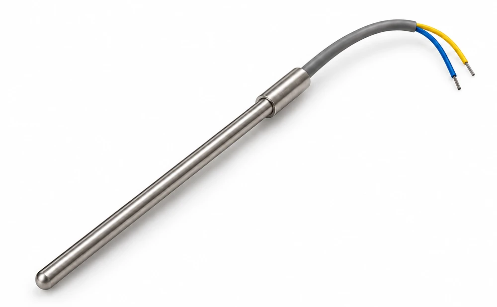
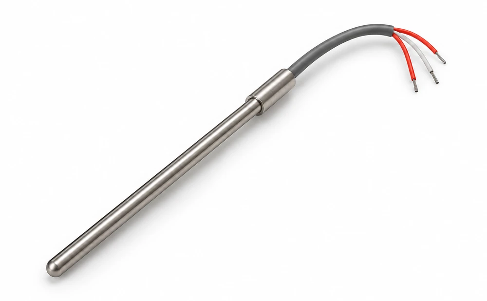
Probe type sensors use a solid stainless steel probe body with an integrated thermocouple or RTD element. The vibration-proof tip design prevents contact bounce and keeps readings stable in machinery subject to mechanical vibration, a common cause of sensor failure in packaging and plastics processing equipment.
Thermocouple ProbeAvailable in Type J or K calibration. Other calibrations available upon request.RTD ProbeRTD cable, 3-wire
Key Design Considerations
Insertion depth: fitting accessories (flanges, stoppers, spring-loaded bayonets) are available for precise, repeatable insertion depth.
TC or RTD: select an RTD (PT100, PT1000, Ni120) over a thermocouple when the process requires a tighter accuracy tolerance or long lead runs.
Common construction options for injection molding, extrusion and general temperature monitoring.
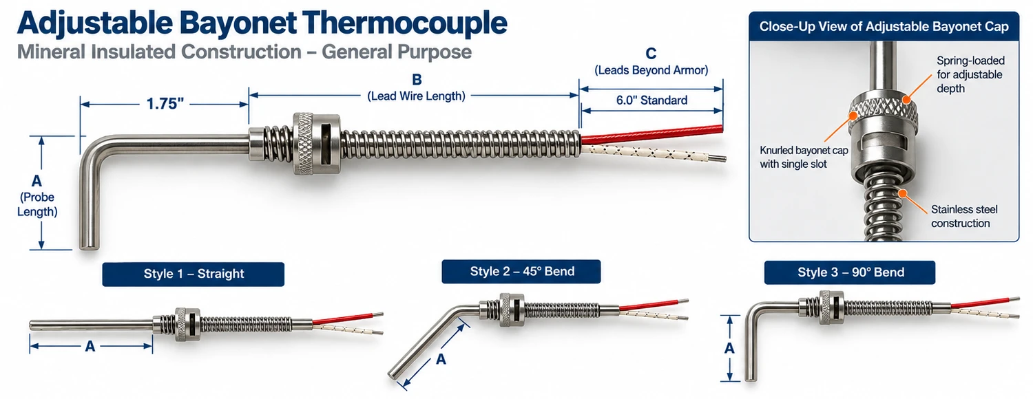
Bayonet Style Thermocouple
Mineral Insulated · General Purpose
Adjustable Bayonet Thermocouple
Bayonet Type J Thermocouples for Plastics Processing
In Stock For immediate delivery
Four standard probe configurations held in stock for injection molding and extrusion applications — ready to ship the same day you order.
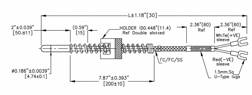
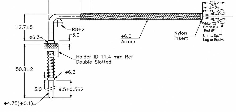
Type JProbe Ø 0.187″ (4.75mm)Termination: Spade lugsCap style: BayonetLeads: 48″ or 72″
Straight Probe OrientationNIT903768 · NIT903771
The probe exits in line with the cable, keeping the assembly low-profile against the barrel or platen. This is the standard choice when clearance around the mounting point is tight, or when the lead run needs to follow a straight path back to the controller.
Part number
Lead length
Availability
NIT903768
48″ (1219mm)
●In stock
NIT903771
72″ (1829mm)
●In stock
90° Probe OrientationNIT903769 · NIT903770
The probe turns 90° off the cable axis, so the lead routes away from the barrel instead of trailing off the end. It’s the better fit wherever axial clearance is limited or the cable needs to run clear of surrounding tooling.
Part number
Lead length
Availability
NIT903770
48″ (1219mm)
●In stock
NIT903769
72″ (1829mm)
●In stock
All four part numbers are on the shelf now. Standard dimensions are compatible with most OEM injection molding and extrusion equipment. Custom probe diameters, lead lengths, and termination styles are available on request.
How to Order
Select the desired options from each category to construct your thermocouple part number.
1KThermocouple Type
–
23Sheath Diameter
–
33Bend Angle
–
4UJunction Type
–
506“A” Dimension (inches)
–
613ASheath Fitting
–
7F1A036-2Lead Wire Type and “B” + “C” Dimensions
1Thermocouple Type
Code
Calibration
J
Type J (Iron-Constantan)
K
Type K (Chromel-Alumel)
E
Type E (Chromel-Constantan)
T
Type T (Copper-Constantan)
2Sheath Diameter
Code
O.D. (inches)
2
1/8″ (0.125″)
3
3/16″ (0.187″)
4
1/4″ (0.250″)
3Bend Angle
Code
Description
1
Straight
2
45° Bend
3
90° Bend
4Junction Type
Code
Description
–
Grounded (Standard)
U
Ungrounded
5“A” Dimension
Specify probe length (A dimension) in inches.
Minimum 1″.
Example: 06 = 6″ probe length
6Sheath Fittings
Code
Description
00
None
13A
7/16″ I.D. single slot spring-loaded bayonet (1 5/8″ nominal length)
Compression fitting with bayonet cap and spring (1/8″ O.D. sheaths only)
7Lead Wire Type and “B” + “C” Dimensions
Code
Description
F1
Fiberglass insulated, solid conductor
F1A
Fiberglass insulated, solid conductor with flexible stainless steel armor
F3
Fiberglass insulated, stranded conductor
T1
Fluoropolymer insulated, solid conductor
T3
Fluoropolymer insulated, stranded conductor
Specify lead wire length (B) in inches (3 digits). Standard “C” length is 6″. For other than 6″, add “-XXX” for C length in inches.
Example: F1A036-2 = 36″ armored lead length with 2″ leads
Melt Bolt Thermocouple
Mineral Insulated Probe · Series MBTC
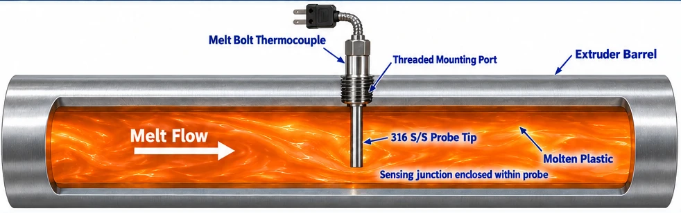
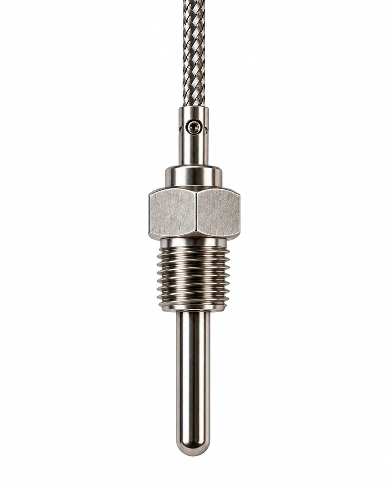
Melt bolt thermocouples measure molten plastic temperature in extrusion heads, die adapters, and related processing equipment. A threaded bolt positions the probe tip at the process wall or within the melt stream, providing temperature feedback for monitoring and control.
316 S/S tip
Mineral insulated construction
Flexible armor or direct connector
Styles & Key Dimensions
Style 1 — Flexible Armor CableOrder code A
Style 2 — Direct ConnectorOrder code B
Typical Application · Plastics Extrusion
The bolt threads into a mounting port on the barrel or die so the 316 S/S probe tip sits in the melt flow, with the sensing junction enclosed within the probe.
How to Order
Select one code from each position below to build the part number.
2Melt Bolt Style
Code
Selection
A
Style 1 (flexible armor cable)
B
Style 2 (direct connector)
3Melt Bolt Length
Code
Selection
03
3″
04
4″
06
6″
07
7″
09
9″
12
12″
14
14″
4Calibration
Code
Selection
J
Type J
K
Type K
T
Type T
E
Type E
W
Type J (special limits)
X
Type K (special limits)
Y
Type T (special limits)
Z
Type E (special limits)
5Tip Diameter
Code
Selection
H
0.125″ OD (standard)
L
0.188″ OD
N
0.250″ OD
For a flush tip, use code H.
6Tip Length
Code
Selection
T
Flush
H
1/8″
U
1/4″
B
3/8″ (standard)
W
1/2″
X
5/8″
Y
3/4″
Z
1″
P
1-1/8″
Q
1-1/4″
7Tip Material
Code
Selection
H
316 S/S
8Junction
Code
Selection
G
Grounded (standard)
U
Ungrounded
E
Exposed
W
Grounded (dual junction)
X
Ungrounded & isolated (dual)
Y
Ungrounded common (dual)
Z
Exposed & isolated (dual)
9Armor Cable Length
Code
Selection
X
No flex armor (Style 2 only)
F
4″ standard (Style 1 only)
2–600
Specify inches (Style 1 only)
Over 600″, contact factory.
10Termination Style
Code
Selection
A
2″ stripped leads (bare ends)
C
Standard male plug (400°F)
D
High temp male plug (660°F)
E
Max temp male plug (800°F)
G
Solid pin plug
H
Standard female jack (400°F)
N
Standard 3-pin plug with ground (400°F)
P
Dual molded male plug (400°F)
Z
Dual molded female jack (400°F)
11Special Features
Code
Selection
—
None
07
Cable clamp
08
BX connector
09
Mating connector
18
Moisture protection boot on connector
23
304 S/S tag with engraved part number
Connector temperature ratings apply to terminations only. Confirm mounting thread, assembly limits, option compatibility, and complete part-number format before ordering.
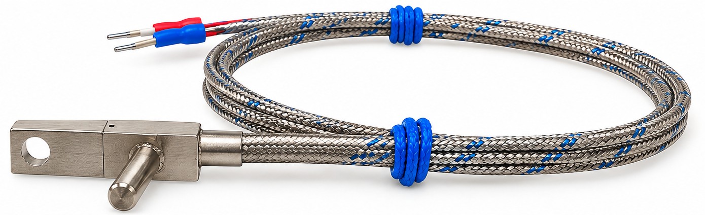
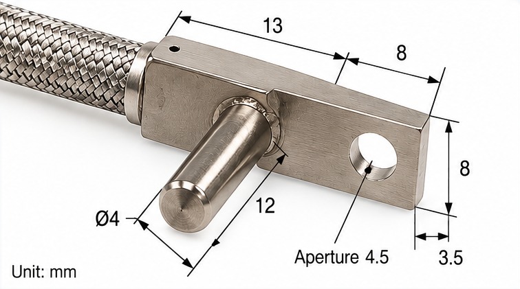
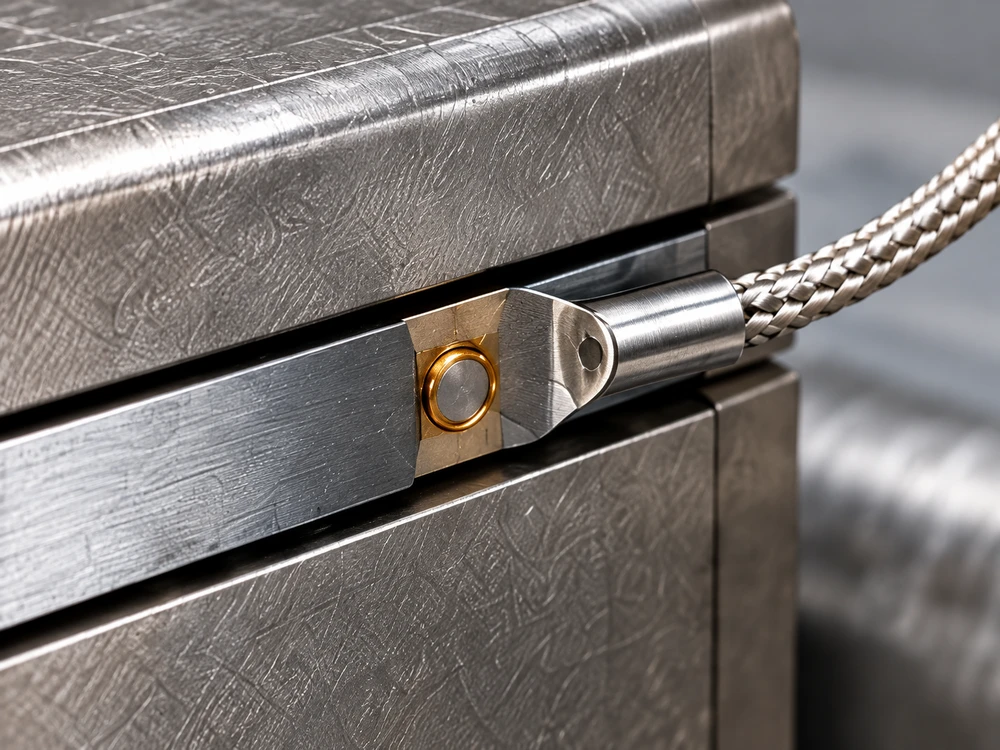
The TEF68 is a lug-mounted probe thermocouple built for hot runner manifolds. A short Ø4 mm probe seats in a drilled hole in the manifold, and an integrated mounting lug secures it with a single screw, holding the junction at a fixed depth in firm contact with the steel.
Because the sensor is locked in place, readings stay consistent through thermal cycling and vibration, and a replacement sensor returns to exactly the same position. A stainless steel braided lead protects the wires from abrasion and heat, and the compact lug fits where space around the manifold is limited.
Typical ApplicationHot runner manifolds, mold plates, and other heated blocks with a drilled sensor bore
Key Design Considerations
Designed for hot runner manifold bore mounting — tip geometry ensures full contact without requiring precise installation torque
Maximum operating temperature: 400°C / 752°F — suitable for most engineering thermoplastic processes
Spring attachment prevents probe bending during manifold assembly — reduces sensor damage and replacement frequency
Available in Type J and K; specify controller compatibility when ordering
Technical Data
Key Dimensions — all dimensions in mm
Dimension
Description
Nominal (mm)
13
Lug length (overall)
13
8
Lug width
8
12
Probe length
12
Ø4
Probe diameter
4
4.5
Mounting hole diameter
4.5
3.5
Hole center to end
3.5
Dimensional
Tip Diameter
Ø4mm
Tip Length
12mm
Min. Extension TC Cable Length
100mm standard (customer-specific available)
Maximum Operating Temperature
400°C / 752°F
Material
Tip & Flange Sheath
SS304 / SS303 (rated 932°F / 500°C)
Electrical
Thermocouple Types
Type J, Type K
Junction
Grounded / Ungrounded
Insulation Resistance (Ungrounded)
≥100 MΩ at 500V-DC (1 sec)
Hot Runner Nozzle TC
Stock MI ThermocouplesIn Stock For immediate delivery
Mineral Insulated Thermocouples for Hot Runner Nozzles
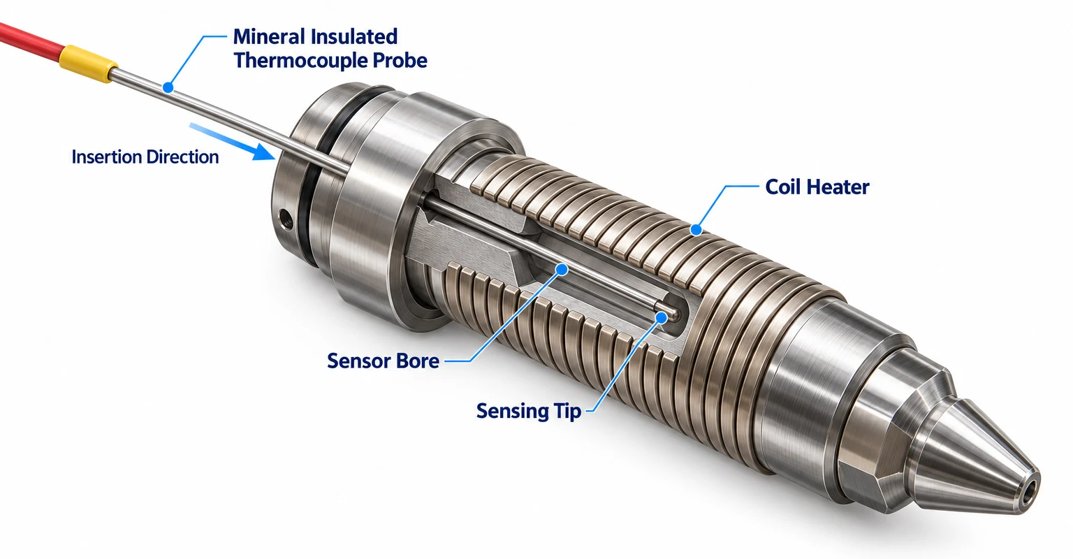
The probe senses nozzle body temperature beneath the coil heater for temperature monitoring and control. Illustrative cutaway
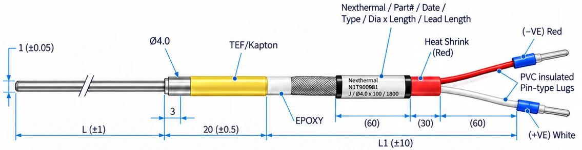
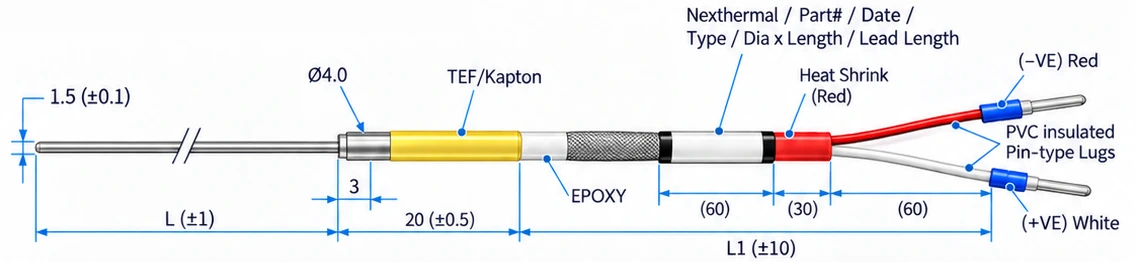
J-type mineral insulated thermocouples sized for hot runner nozzles, available in 1.0 mm and 1.5 mm probe diameters and four standard probe lengths. Every part number below is stocked for immediate delivery.
Specifications — all dimensions in mm
Thermocouple Type
J-type, ungrounded
Max Temperature
300°C
Sheath Material
SS316
Transition
Ø4.0 mm, 20 mm long
Lead Length (L1)
1800 mm (±10)
Lead Wires
PVC insulated, pin-type lugs
Polarity
+VE white / −VE red
Identification
Labeled with part #, date, type, size
1.0 mm Diameter Probe · Ø1.0 (±0.05)
1.0 mm probe part numbers
Part #
Probe Ø
L (mm)
L1 (mm)
Availability
NIT900981
1.0 mm
100
1800
In stock
NIT900982
1.0 mm
150
1800
In stock
NIT900983
1.0 mm
200
1800
In stock
NIT900984
1.0 mm
250
1800
In stock
1.5 mm Diameter Probe · Ø1.5 (±0.1)
1.5 mm probe part numbers
Part #
Probe Ø
L (mm)
L1 (mm)
Availability
NIT900986
1.5 mm
100
1800
In stock
NIT900987
1.5 mm
150
1800
In stock
NIT900988
1.5 mm
200
1800
In stock
NIT900989
1.5 mm
250
1800
In stock
Compression Fitting
Adjustable Insertion Depth
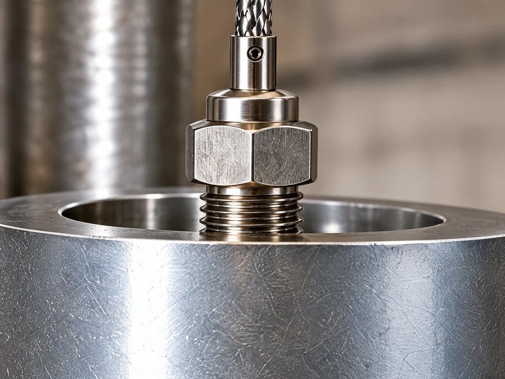
A straight probe passed through a threaded compression fitting, allowing insertion depth to be set at installation and sealed against the process. Well suited to tanks, pipes, ovens, and process vessels where a secure, leak-resistant mount is needed.
Typical ApplicationTank, pipe or process vessel
Technical Data
Dimensional — Compression Fitting
Common Fitting Threads
1/8″ NPT M5 × 8 mm M6 × 8 mm M6 × 10 mm
Insertion Depth
Adjustable at installation
Electrical
Thermocouple Types
Type J Type K
Junction
Grounded / Ungrounded
Ring Lug
Surface Temperature
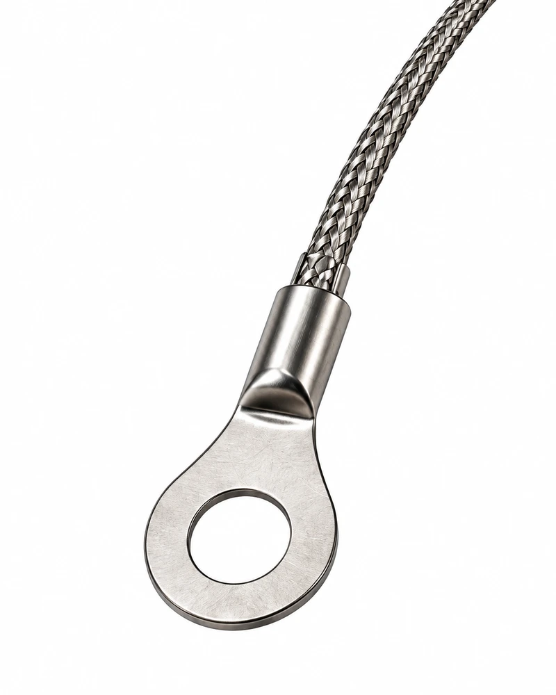
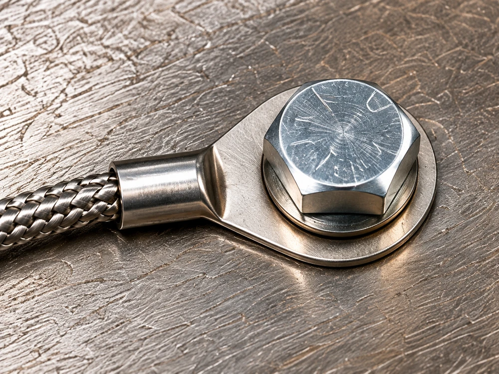
The junction is attached to a metal ring terminal that mounts directly under an existing screw or bolt. This gives a simple, low-cost way to measure surface temperature on platens, molds, motors, heat sinks, and equipment housings.
Typical ApplicationPlatens, molds, motors or heat sinks
Technical Data
Dimensional — Washer Type
Washer (ID × OD × Thickness)
Ø4.5 mm × Ø11 mm × 4 mm Ø6.3 mm × Ø12 mm × 3.5 mm Ø6.3 mm × Ø12 mm × 5 mm Ø5.3 mm × Ø10 mm × 5 mm
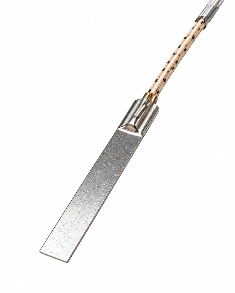
The junction is bonded to a thin, flat metal strip that slips between two surfaces, such as a band heater and barrel or between platens. Its low profile and fast response make it ideal where there is no room for a probe or drilled hole.
Typical ApplicationBand heater and barrel or between platens
Lead Terminations
Terminations · Cables · Connectors
Thermocouple & RTD Lead Terminations
Leads · Lugs · Plugs
Choose the lead termination that suits your controller, panel, or instrument, from bare wire for direct wiring to color-coded plugs for fast sensor changes.
Image
Termination
Description
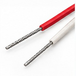
Stripped Leads
Bare wire ends for direct connection to terminal blocks or controllers. The simplest, lowest-cost option, with no added connection point in the circuit.
Spade Lugs
Insulated spade lugs that slide under a loosened terminal screw, allowing quick connection and removal without fully backing the screw out.
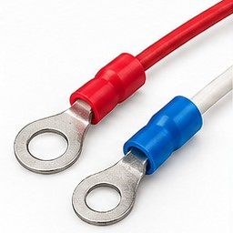
Ring Lugs
Insulated ring lugs that fit fully around a screw or stud, so the connection cannot slip off under vibration.
Miniature PlugANSI color coded
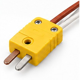
Compact plug color coded to ANSI standard for the thermocouple type (Type J or K). Ideal for handheld instruments, portable readouts, and tight spaces.
Standard PlugANSI color coded
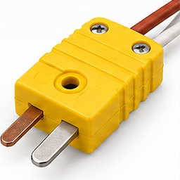
Full-size plug color coded to ANSI standard (Type J or K), with a heavier body and pins for panel and industrial connections.
High Temperature Ceramic Plug
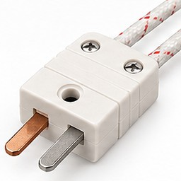
Ceramic-bodied plug for connections close to the heat source, where standard thermoplastic plugs would soften or degrade (Type J or K).
Lead Protection
Springs · Armor · Sleeves
Image
Option
Description
Spring
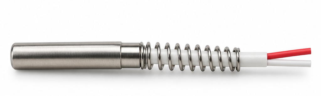
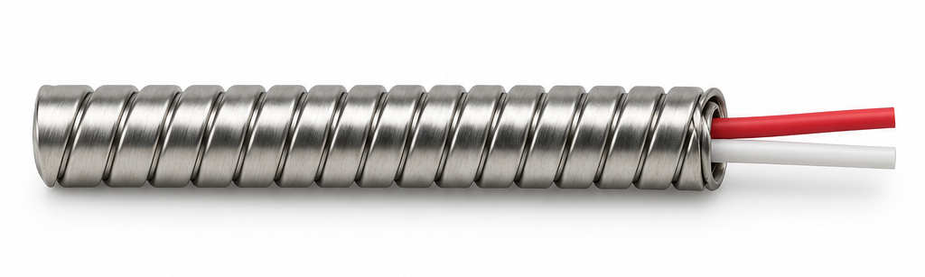
Prevents cable fatigue at exit point; standard on bolt and bayonet-mount designs
Armor Cable
Mechanical protection for high-vibration environments
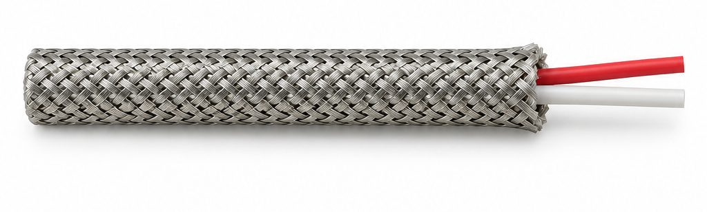
Braided Metal Sleeve
Flexible metal sheath for abrasion and crush protection
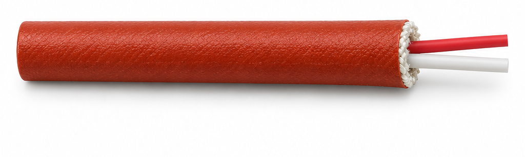
Silicon Coated Fiberglass Sleeve
260°C / 500°F chemical and temperature resistance
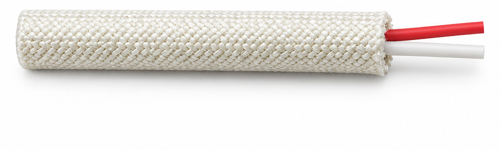
High Temperature Fiberglass Sleeve
450°C / 842°F for extreme proximity to heat source
Potting / Sealing Options
Ceramic · Epoxy · Silicone
Potting / Seal
Max. Temperature
Transition Adaptor
Ceramic Potting
538°C / 1,000°F
Epoxy Potting
315°C / 600°F
Silicone Potting
260°C / 500°F
High-Temperature Silicone Potting
343°C / 650°F
Lead Color Codes
ANSI · IEC · BS · DIN
Thermocouple Lead Color Code Standards
Color coding varies by regional standard. Specify the correct standard for your controller interface and connector type when ordering. Mismatched polarity introduces a systematic measurement error that is difficult to detect in the field.
TC Type
Standard
Positive (+) Lead
Negative (−) Lead
Type J
ANSI
White
Red
Type J
IEC
Black
White
Type K
ANSI
Yellow
Red
Type K
IEC
Green
White
Type K
BS
Brown
Blue
Type K
DIN
Red
Green
For other standards (NFC, JIS, DIN), contact Nexthermal.
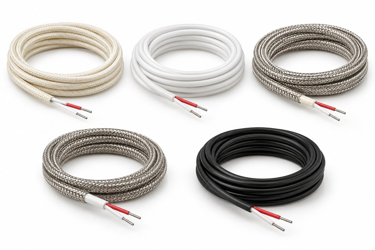
Thermocouple Extension Wire
Type J · Type K
Extension cable and lead protection selection directly affects sensor longevity and signal integrity. Specify cable type and temperature rating based on the thermal environment at the sensor exit point — not just at the measuring tip.
Type J and Type K wire configurations in 20 and 24 AWG, with solid or stranded conductors and a choice of insulation and protection.
Type J / Type K20 / 24 AWG36 configurations
Representative insulation and protection styles; colors and appearance may vary by configuration.
Part Number Format
NX-EW-J-24-SOL-FG-SS
NX-EW
Nexthermal extension wire
J / K
Calibration
20 / 24
AWG
SOL / STR
Solid / stranded
FG / FP / PVC
Fiberglass / fluoropolymer / PVC
SS
Stainless steel braid (omit when not required)
New numbers are proposed for this catalog and are unique within these 36 configurations. Source part numbers are retained for cross-reference.
Configurations
Type J
18 configurations
Type J thermocouple extension wire configurations
Nexthermal Part Number
Source Part Number
Conductor
Insulation / Protection
Wire Gauge
NX-EW-J-24-SOL-FG
J24GG
Solid
Fiberglass
24 AWG
NX-EW-J-24-STR-FG
J24-7-GG
Stranded
Fiberglass
24 AWG
NX-EW-J-20-SOL-FG
J20GG
Solid
Fiberglass
20 AWG
NX-EW-J-20-STR-FG
J20-7-GG
Stranded
Fiberglass
20 AWG
NX-EW-J-24-SOL-FP
J24TT
Solid
Fluoropolymer
24 AWG
NX-EW-J-24-STR-FP
J24-7-TT
Stranded
Fluoropolymer
24 AWG
NX-EW-J-20-SOL-FP
J20TT
Solid
Fluoropolymer
20 AWG
NX-EW-J-20-STR-FP
J20-7-TT
Stranded
Fluoropolymer
20 AWG
NX-EW-J-24-SOL-FG-SS
J24GGSS
Solid
Fiberglass with stainless steel braid
24 AWG
NX-EW-J-24-STR-FG-SS
J24-7-GGSS
Stranded
Fiberglass with stainless steel braid
24 AWG
NX-EW-J-20-SOL-FG-SS
J20GGSS
Solid
Fiberglass with stainless steel braid
20 AWG
NX-EW-J-20-STR-FG-SS
J20-7-GGSS
Stranded
Fiberglass with stainless steel braid
20 AWG
NX-EW-J-24-SOL-FP-SS
J24TTSS
Solid
Fluoropolymer with stainless steel braid
24 AWG
NX-EW-J-24-STR-FP-SS
J24-7-TTSS
Stranded
Fluoropolymer with stainless steel braid
24 AWG
NX-EW-J-20-SOL-FP-SS
J20TTSS
Solid
Fluoropolymer with stainless steel braid
20 AWG
NX-EW-J-20-STR-FP-SS
J20-7-TTSS
Stranded
Fluoropolymer with stainless steel braid
20 AWG
NX-EW-J-20-SOL-PVC
JX20PP
Solid
PVC
20 AWG
NX-EW-J-20-STR-PVC
JX20-7-PP
Stranded
PVC
20 AWG
Type K
18 configurations
Type K thermocouple extension wire configurations
Nexthermal Part Number
Source Part Number
Conductor
Insulation / Protection
Wire Gauge
NX-EW-K-24-SOL-FG
K24GG
Solid
Fiberglass
24 AWG
NX-EW-K-24-STR-FG
K24-7-GG
Stranded
Fiberglass
24 AWG
NX-EW-K-20-SOL-FG
K20GG
Solid
Fiberglass
20 AWG
NX-EW-K-20-STR-FG
K20-7-GG
Stranded
Fiberglass
20 AWG
NX-EW-K-24-SOL-FP
K24TT
Solid
Fluoropolymer
24 AWG
NX-EW-K-24-STR-FP
K24-7-TT
Stranded
Fluoropolymer
24 AWG
NX-EW-K-20-SOL-FP
K20TT
Solid
Fluoropolymer
20 AWG
NX-EW-K-20-STR-FP
K20-7-TT
Stranded
Fluoropolymer
20 AWG
NX-EW-K-24-SOL-FG-SS
K24GGSS
Solid
Fiberglass with stainless steel braid
24 AWG
NX-EW-K-24-STR-FG-SS
K24-7-GGSS
Stranded
Fiberglass with stainless steel braid
24 AWG
NX-EW-K-20-SOL-FG-SS
K20GGSS
Solid
Fiberglass with stainless steel braid
20 AWG
NX-EW-K-20-STR-FG-SS
K20-7-GGSS
Stranded
Fiberglass with stainless steel braid
20 AWG
NX-EW-K-24-SOL-FP-SS
K24TTSS
Solid
Fluoropolymer with stainless steel braid
24 AWG
NX-EW-K-24-STR-FP-SS
K24-7-TTSS
Stranded
Fluoropolymer with stainless steel braid
24 AWG
NX-EW-K-20-SOL-FP-SS
K20TTSS
Solid
Fluoropolymer with stainless steel braid
20 AWG
NX-EW-K-20-STR-FP-SS
K20-7-TTSS
Stranded
Fluoropolymer with stainless steel braid
20 AWG
NX-EW-K-20-SOL-PVC
KX20PP
Solid
PVC
20 AWG
NX-EW-K-20-STR-PVC
KX20-7-PP
Stranded
PVC
20 AWG
Thermocouple Accessories
Bayonet Adaptors · Plugs & Receptacles
Bayonet adaptors and thermocouple connectors for mounting and connecting thermocouple and RTD sensors.
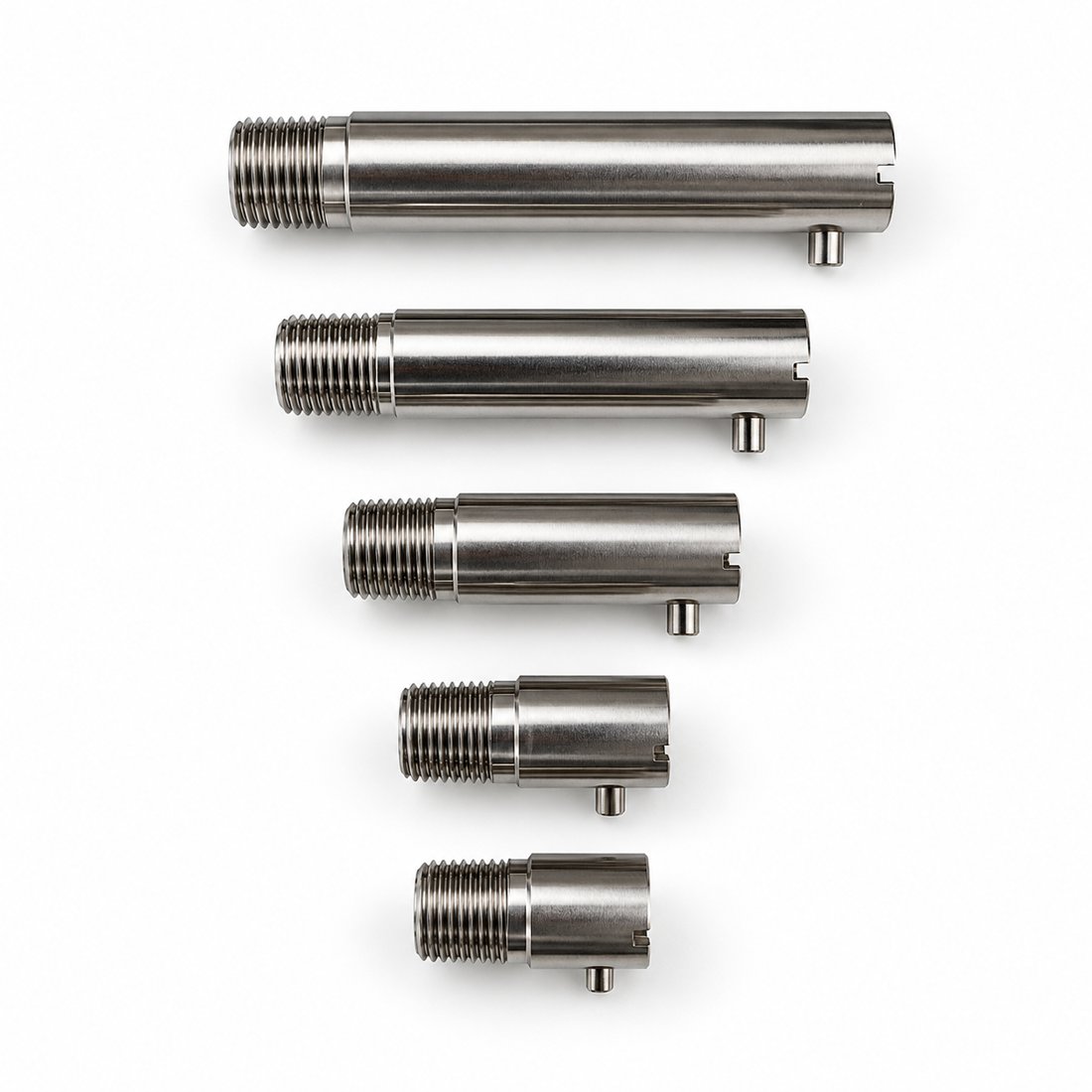
Bayonet Adaptors
Bayonet adaptors provide the threaded mounting point for a compatible bayonet cap, securing the sensor assembly at the installation point.
Representative single-pin bayonet adaptors in graduated lengths. Select dimensions and thread details from the tables below.
Part numbers: NX-BA-N18 1/8″ NPT family · NX-BA-U38 3/8-24 straight-thread family · NX-BA-M metric family. The final three digits identify an individual configuration.
1/8″ NPT
Stainless Steel · 10 configurations
Material
Stainless steel
Thread
1/8″ NPT
Outside diameter
7/16″
Locking
Single pin
Cap
Standard bayonet cap
Part Number
Length
NX-BA-N18-001
7/8″
NX-BA-N18-002
1″
NX-BA-N18-003
1-1/4″
NX-BA-N18-004
1-3/8″
NX-BA-N18-005
1-1/2″
NX-BA-N18-006
2″
NX-BA-N18-007
2-1/4″
NX-BA-N18-008
2-1/2″
NX-BA-N18-009
3″
NX-BA-N18-010
3-1/2″
3/8-24 Straight Thread
Zinc-Plated Steel · 8 configurations
Material
Zinc-plated steel
Thread
3/8-24 straight
Outside diameter
7/16″
Locking
Single pin
Cap
Standard bayonet cap
Part Number
Length
NX-BA-U38-001
7/8″
NX-BA-U38-002
1-1/4″
NX-BA-U38-003
1-3/8″
NX-BA-U38-004
1-1/2″
NX-BA-U38-005
2-1/4″
NX-BA-U38-006
2-1/2″
NX-BA-U38-007
3″
NX-BA-U38-008
3-1/2″
Metric Threads
Stainless Steel · 10 configurations
Material
Stainless steel
Threads
M12 and M14
Locking
Double pin
Cap
Appropriate metric double-slot bayonet cap
Part Number
Thread Size
Pitch
Length
NX-BA-M-001
M12
1.0 mm
1″
NX-BA-M-002
M12
1.0 mm
1-1/2″
NX-BA-M-003
M12
1.0 mm
2-1/2″
NX-BA-M-004
M12
1.5 mm
1″
NX-BA-M-005
M12
1.5 mm
1-1/2″
NX-BA-M-006
M12
1.5 mm
2-1/2″
NX-BA-M-007
M12
1.75 mm
1″
NX-BA-M-008
M12
1.75 mm
2-1/2″
NX-BA-M-009
M14
1.0 mm
1-1/2″
NX-BA-M-010
M14
1.5 mm
2″
Other thread sizes and lengths available.
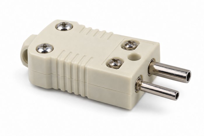
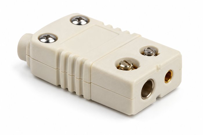
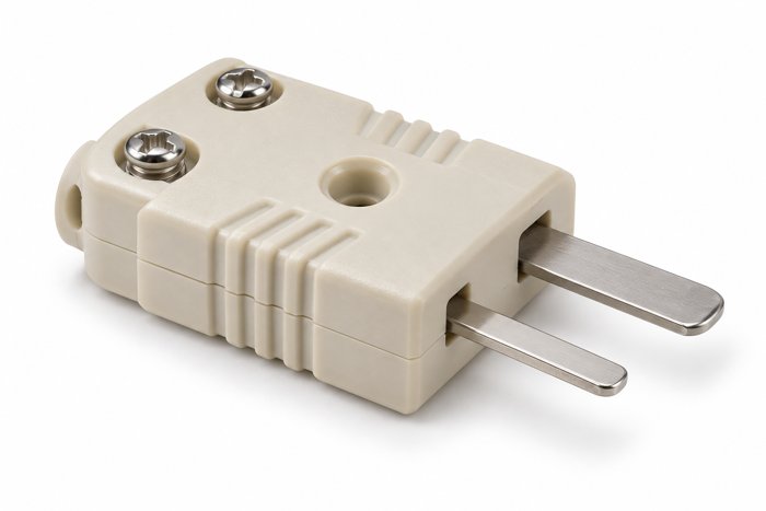
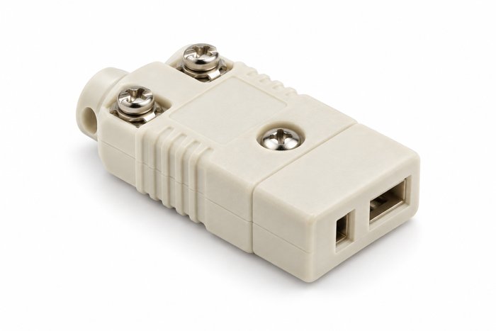
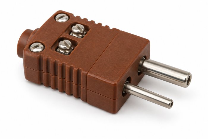
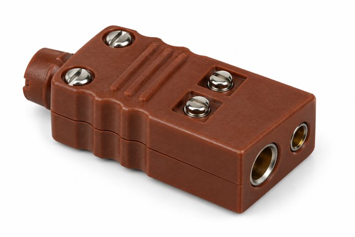
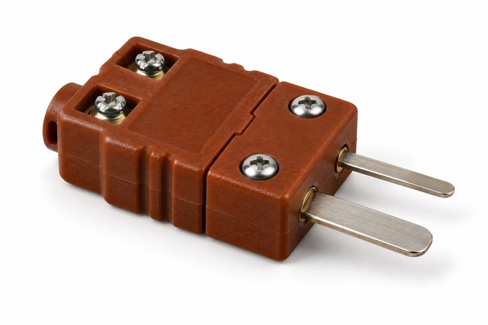
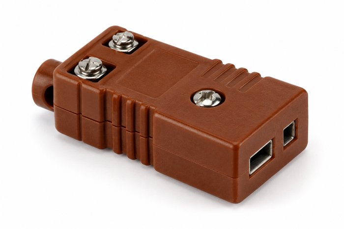
Thermocouple Plugs and Receptacles
Standard-size and miniature thermocouple connectors in Type J, K, T, and E calibrations. Choose thermoplastic construction for the 400°F range or thermoset construction for the 660°F range.
Part number format: NX-TC-400-STD-P-J · 400 / 660 = temperature rating in °F · STD / MIN = standard size / miniature · P / R = male plug / female receptacle · J / K / T / E = calibration.
Standard Temperature · 400°F
Thermoplastic · 16 configurations
Standard Size Male Plug
Thermoplastic · Hollow Pin
Part Number
Calibration
NX-TC-400-STD-P-J
Type J
NX-TC-400-STD-P-K
Type K
NX-TC-400-STD-P-T
Type T
NX-TC-400-STD-P-E
Type E
Standard Size Female Receptacle
Thermoplastic
Part Number
Calibration
NX-TC-400-STD-R-J
Type J
NX-TC-400-STD-R-K
Type K
NX-TC-400-STD-R-T
Type T
NX-TC-400-STD-R-E
Type E
Miniature Male Plug
Thermoplastic
Part Number
Calibration
NX-TC-400-MIN-P-J
Type J
NX-TC-400-MIN-P-K
Type K
NX-TC-400-MIN-P-T
Type T
NX-TC-400-MIN-P-E
Type E
Miniature Female Receptacle
Thermoplastic
Part Number
Calibration
NX-TC-400-MIN-R-J
Type J
NX-TC-400-MIN-R-K
Type K
NX-TC-400-MIN-R-T
Type T
NX-TC-400-MIN-R-E
Type E
High Temperature · 660°F
Thermoset · 16 configurations
Standard Size Male Plug
Thermoset · Hollow Pin
Part Number
Calibration
NX-TC-660-STD-P-J
Type J
NX-TC-660-STD-P-K
Type K
NX-TC-660-STD-P-T
Type T
NX-TC-660-STD-P-E
Type E
Standard Size Female Receptacle
Thermoset
Part Number
Calibration
NX-TC-660-STD-R-J
Type J
NX-TC-660-STD-R-K
Type K
NX-TC-660-STD-R-T
Type T
NX-TC-660-STD-R-E
Type E
Miniature Male Plug
Thermoset
Part Number
Calibration
NX-TC-660-MIN-P-J
Type J
NX-TC-660-MIN-P-K
Type K
NX-TC-660-MIN-P-T
Type T
NX-TC-660-MIN-P-E
Type E
Miniature Female Receptacle
Thermoset
Part Number
Calibration
NX-TC-660-MIN-R-J
Type J
NX-TC-660-MIN-R-K
Type K
NX-TC-660-MIN-R-T
Type T
NX-TC-660-MIN-R-E
Type E
Images represent connector styles; housing colors may vary by calibration. Temperature ratings follow the supplied reference.
Temperature Sensor FAQ
Selection, installation, and sizing guidance for thermocouples, RTDs, and thermistors.
Sensor Selection
What’s the basic difference between a thermocouple, an RTD, and a thermistor?
A thermocouple generates its own small voltage from the junction of two dissimilar metals, with the voltage varying with temperature — no excitation power required. An RTD (resistance temperature detector) uses a precision metal element (typically platinum) whose electrical resistance increases predictably with temperature, requiring an excitation current to read. A thermistor uses a ceramic semiconductor whose resistance changes sharply with temperature — usually decreasing (NTC) — giving high sensitivity over a narrower range.
Why it matters
Treating these as interchangeable “temperature sensors” without understanding the underlying measurement principle leads to specifying the wrong device for the accuracy, range, or environment actually required — each has a distinct sweet spot, not a universal one.
Which sensor type offers the best accuracy?
RTDs generally offer the best combination of accuracy and long-term stability, commonly achieving ±0.1°C to ±0.3°C with a Class A platinum element. Thermistors can be more accurate than RTDs over a narrow temperature band (sometimes ±0.05°C to ±0.2°C) but lose that advantage outside their optimized range. Thermocouples are the least inherently accurate of the three, typically ±0.5°C to ±2°C depending on type and calibration, but remain the most practical choice at temperature extremes RTDs and thermistors can’t reach.
Why it matters
Specifying a thermocouple for a life-science or semiconductor application needing tight, stable control leaves accuracy on the table that an RTD would have delivered, while specifying an RTD or thermistor for a very high-temperature furnace application may exceed what those sensor types can survive.
What temperature range does each sensor type cover?
Thermocouples cover the widest overall range, from roughly -270°C to as high as 1800°C depending on type. RTDs typically operate from about -200°C to 850°C (platinum elements). Thermistors cover the narrowest range, generally -50°C to 300°C, with their best accuracy concentrated in an even tighter window within that span.
Why it matters
Choosing a thermistor for its excellent accuracy without checking that your process stays within its rated span is a common mistake — push a thermistor near its upper limit and both accuracy and long-term stability degrade well before it reaches a thermocouple’s practical ceiling.
How do response time and thermal mass factor into sensor selection?
Thermistors generally respond fastest due to their small physical size and low thermal mass, followed by thin-film RTDs, with wire-wound RTDs and larger-diameter thermocouple probes responding more slowly. A bare-wire or exposed-junction thermocouple, however, can respond extremely quickly, often faster than a comparably sized RTD, because it lacks the sheath and fill material that slow down a sheathed probe.
Why it matters
Selecting a large-diameter sheathed sensor for a fast-cycling process (such as extrusion temperature control) introduces control lag that shows up as overshoot and oscillation in the control loop, even though the sensor’s rated accuracy looks fine on paper.
Which sensor is typically the most cost-effective choice?
Base-metal thermocouples (especially Type K and J) are generally the lowest-cost option per sensor, thermistors are moderate in cost but require more careful signal conditioning for linearization, and RTDs are typically the highest upfront cost but often the lowest total cost of ownership where long-term accuracy and stability reduce recalibration and downtime.
Why it matters
Choosing the lowest sensor purchase price without accounting for calibration frequency, drift, and replacement rate over the equipment’s service life often costs more in the long run than specifying the RTD or thermistor that was actually the better fit for the application’s accuracy and stability requirements.
Thermocouples, RTDs & Thermistors
Which thermocouple type (J, K, T, E, N, R/S/B) should I choose?
Type K is the general-purpose default for a wide range (-200°C to 1260°C) and moderate cost. Type J suits a narrower range with good sensitivity but degrades in oxidizing atmospheres above ~760°C. Type T offers strong accuracy and stability at low/cryogenic temperatures. Type E gives the highest output signal of the base metal types, useful in electrically noisy environments. Type N resists oxidation and drift better than K at high temperatures. Types R, S, and B use platinum/rhodium for the highest-temperature, highest-stability applications (up to ~1700–1800°C) at significantly higher cost.
Why it matters
Defaulting to Type K out of habit in a cryogenic process (where Type T excels) or a high-temperature furnace (where R/S/B is warranted) trades away accuracy or service life that the correct type would have delivered for a similar overall system cost.
Should I specify a grounded or an ungrounded junction?
A grounded junction is bonded to the sheath and responds faster, which suits direct immersion in metallic, conductive bores. An ungrounded junction is electrically isolated from the sheath and is preferred in hot runner controllers and multi-zone systems to prevent ground loops.
Why it matters
Grounded junctions in a multi-zone system can create ground loops that show up as noisy or unstable readings. Response speed and electrical isolation have to be balanced for each application.
What’s the difference between 2-wire, 3-wire, and 4-wire RTD configurations?
A 2-wire RTD is the simplest but least accurate, since lead-wire resistance adds directly to the measured signal. A 3-wire configuration is the industrial standard, using a bridge circuit to cancel out lead-wire resistance as long as all three leads are equal length and gauge. A 4-wire configuration eliminates lead-wire resistance error entirely and is used where the highest possible accuracy is required, such as calibration-grade or life-science instrumentation.
Why it matters
Specifying 2-wire RTDs on long lead runs (common when the transmitter is far from the sensing point) introduces a measurement error that scales with cable length — a problem that’s easy to overlook until calibration checks reveal an offset that traces back to wiring, not the sensor.
When should I choose a PT1000 instead of a PT100?
Both are platinum RTDs with the same stability and accuracy. The PT1000 has ten times the resistance (1,000 Ω at 0°C), so lead wire resistance has less effect on the reading. It is the better choice for long lead runs, remote sensing and electrically noisy environments. The PT100 is the most widely specified industrial standard and covers a higher range, up to 600°C.
Why it matters
On a long cable run, wire resistance adds to the sensor resistance and reads as extra temperature. A higher-resistance element, or a 3-wire or 4-wire connection, reduces that error.
When is a Ni120 RTD the right choice?
Ni120 RTDs use a nickel element with a steeper resistance-versus-temperature curve than platinum, which gives higher sensitivity over 32°F to 356°F (0°C to 180°C). They are used for seal bars, laboratory equipment, medical devices and food processing equipment that run at moderate temperatures.
Why it matters
Within its range, the Ni120 resolves small temperature changes well and is a cost-effective option for precision control.
What’s the difference between NTC and PTC thermistors, and which should I use?
NTC (negative temperature coefficient) thermistors decrease in resistance as temperature rises and are the standard choice for precise point-temperature measurement and control. PTC (positive temperature coefficient) thermistors increase sharply in resistance at a threshold temperature and are used mainly for over-temperature protection, self-resetting fuses, or inrush current limiting rather than continuous measurement.
Why it matters
Selecting a PTC thermistor for continuous temperature measurement (rather than threshold protection) doesn’t give you a usable, linear temperature signal across your process range — PTC devices are built for a sharp trip point, not a smooth measurement curve.
What is self-heating error, and does it affect RTDs and thermistors?
Both RTDs and thermistors require an excitation current to be measured, and that current dissipates a small amount of power in the sensing element itself, slightly raising its temperature above the true process temperature — an effect called self-heating error. It’s more pronounced in thermistors (due to their higher resistance and smaller thermal mass) than in RTDs, and is minimized by using the lowest practical excitation current and adequate heat-sinking to the process.
Why it matters
Self-heating error is a small but real accuracy-limiting factor that’s easy to overlook when specifying a thermistor for a tight-tolerance application — in still air or low-thermal-mass installations, it can be large enough to matter for life-science or calibration-grade requirements.
Construction & Installation
Which sensor body style do I need?
The body style follows the mounting geometry and heat source. MI thermocouples suit high-temperature, high-vibration installations and bores that need a formed probe. Probe types suit bore immersion and surface contact. The TEF68 is designed for hot runner manifolds. Bolt types thread into a tapped bore at the heat source. Washer and lug types mount under a fastener on flat surfaces.
Why it matters
The body style decides how well the sensing tip contacts the part. Poor contact causes measurement lag and readings that do not reflect the true temperature.
Which sheath material should I choose?
SS304 and SS316 sheaths are rated to 932°F (500°C). Inconel 600 is rated to 1,292°F (700°C) and is used for MI probes in higher-temperature applications. Brass is available for washer type sensors in lower-corrosion environments.
Why it matters
A sheath operated above its rating degrades and eventually fails. The sheath has to be rated to the maximum process temperature plus a margin for thermal cycling.
How does probe or sheath diameter affect installation and response time?
A smaller-diameter probe generally responds faster and fits into tighter installation points, but is also more fragile and may be limited in maximum operating temperature or pressure rating compared to a larger-diameter sheath. Match the probe diameter to the actual mounting boss, thermowell, or bore size available, not just the fastest response time on the data sheet.
Why it matters
Specifying an undersized probe diameter purely for faster response, without confirming it fits the available thermowell or has adequate mechanical strength for the process pressure, can lead to an installation that requires field modification or a probe that’s vulnerable to damage in service.
Can an MI thermocouple be bent to fit my installation?
Yes. The fully annealed construction allows MI thermocouples to be bent and formed to complex geometries without damaging the sheath. The minimum bending radius is 3x the probe OD. Straight, L-bend, multi-bend and custom preformed shapes are available.
Why it matters
Forming the probe to the installation lets the tip reach the measurement point without strain on the sheath or the transition head.
Which tip profile should I specify?
A round tip is for bore immersion and maximizes axial contact. A flat tip is for surface contact on plates, platens and flat mating surfaces. A 120° angled tip seats in conical recesses and maximizes contact area in tapered bores.
Why it matters
Matching the tip to the bottom of the bore or the mating surface removes the air gap that slows response and lowers the reading.
Why does immersion depth matter for accurate readings?
Any sensor needs adequate immersion into the process (commonly a rule of thumb of 8–10x the probe diameter, or per the manufacturer’s specification) so that heat conducted back up the sheath toward the cooler ambient air doesn’t pull the sensing tip’s reading below the true process temperature — an effect known as stem conduction error.
Why it matters
Insufficient immersion depth is a frequently overlooked source of a consistent, repeatable temperature offset that looks like sensor drift or miscalibration but is actually a mechanical installation issue — recalibrating the sensor won’t fix an immersion-depth problem.
How do I get the same insertion depth on every machine?
Spring-loaded bayonet caps, flanges and stoppers position the sensor tip at a defined depth, so every assembly in a production run is installed the same way. On bolt type sensors, the thread size is matched to the tapped bore so the tip reaches the bore bottom at the designed depth.
Why it matters
If insertion depth varies between machines, each one reads a slightly different temperature and the process cannot be repeated from machine to machine.
How does sensor placement affect accuracy in a control loop?
Position the sensor as close as practical to the true point where temperature control matters — the actual process zone or product surface — rather than a convenient but thermally offset location such as a heater’s back side or a distant wall of the enclosure.
Why it matters
A sensor placed away from the true control point introduces lag and offset into the control loop that no amount of PID tuning can fully correct — this is the same placement issue that causes life-science incubation or analyzer temperatures to silently drift out of tolerance even when the controller reports a stable setpoint.
Wiring, Connectors & Signal
How do lead wire length and extension wire type affect thermocouple accuracy?
Thermocouples must use extension or compensating wire made of the same (or matched) alloy pair as the thermocouple type all the way to the cold-junction reference point — substituting standard copper wire, or mixing extension wire types, introduces uncontrolled junctions that corrupt the reading. RTDs and thermistors are less sensitive to lead wire alloy but still need the wiring configuration (2/3/4-wire) matched correctly, as noted above.
Why it matters
Using the wrong extension wire on a thermocouple is one of the most common and hardest-to-diagnose sources of temperature reading errors, because the system may still produce a plausible-looking number that’s simply wrong, rather than an obvious fault.
Why does the lead color code standard matter?
Color coding varies by regional standard. For example, a Type K positive lead is yellow under ANSI, green under IEC, brown under BS and red under DIN. Nexthermal supplies ANSI, IEC, DIN, JIS and BS color coding with matching miniature or standard connectors.
Why it matters
Mismatched polarity introduces a systematic measurement error that is difficult to detect in the field, because the controller still shows a plausible temperature.
How do I prevent electrical noise and ground loops?
Use ungrounded junctions with SS-braided shielded cable, with the shields isolated at the sensor end. This prevents ground loops in multi-zone controller systems. Insulation resistance of ≥100 MΩ at 500V-DC is standard, and ≥1 GΩ is available on request for noise-sensitive applications.
Why it matters
Electrical noise shows up as unstable or drifting readings, which the controller then acts on. The heater output follows the noise instead of the real temperature.
What termination and connector options are available, and how does that affect environmental sealing?
Common options include standard miniature or standard thermocouple connectors, potted/epoxy-sealed leads, and moisture-resistant molded connectors — following the same environmental-matching logic used for heater terminations. Choose sealed, potted, or IP-rated connectors for washdown, humid, or submerged installations, and confirm lead insulation is rated for any high-ambient-temperature area the leads pass through.
Why it matters
As with heater terminations, the sensor’s connector and lead seal is frequently the actual point of failure in wet or high-vibration environments, not the sensing element itself — a mismatch here shows up as intermittent or drifting readings that get misdiagnosed as sensor failure.
No matching questions
Try a different term, or send the application details and an engineer will answer directly.
Question not answered here?
Send the operating temperature, mounting point and controller type and an engineer will respond.